How to flash a custom firmware on a NEO Coolcam WiFi plug without soldering
Excerpt
In this post I will show how I flashed a custom firmware on a NEO Coolcam smart WiFi plug. No soldering is required, and the plug will not be damaged since a complete disassembly is not required.
⚠️⚡ DANGER! ⚡⚠️
230V AC or 110V AC).
The plug should never be connected to the mains at any time until the procedure is finished and the plug has been reassembled back as it came out of the box!
The plug
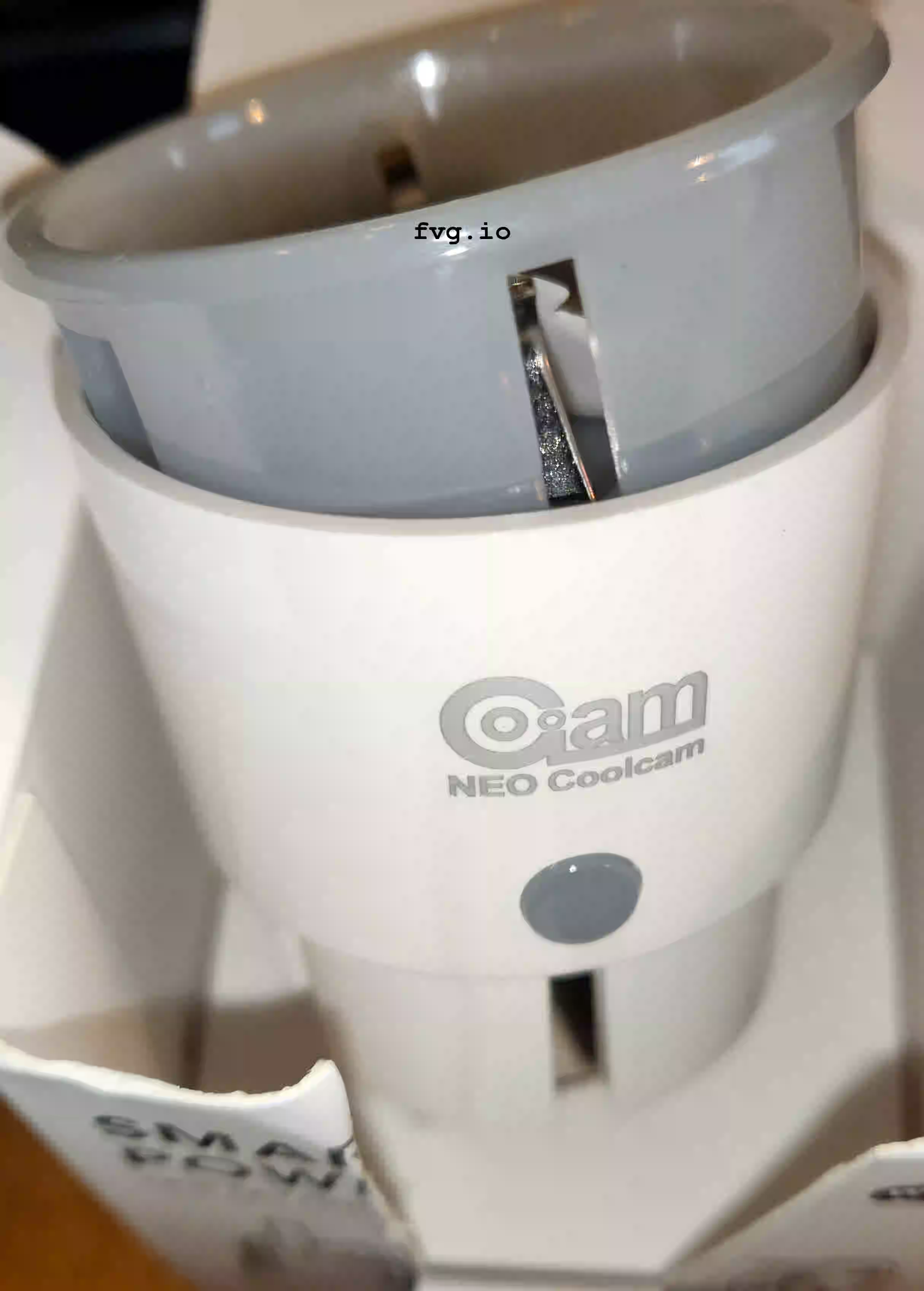
I tried a couple of WiFi smart plugs before I discovered the NEO Coolcam plugs. I chose this particular plug for several reasons:
- It’s small: wherever you can fit a standard EU plug, you can most likely also fit a NEO Coolcam
- It’s powerful: up to 16A of current or 3.68 kW of power
- Has power monitoring: it’s not very advanced, but it works well enough for my use
- It’s cheap: at the time of writing, you can get one for less than 10$, which is less than many other models that come without power monitoring
The problem
I want my smart devices to work with Home Assistant without relying on a proprietary cloud service or any service located outside my local network. One strategy to achieve that is to replace the firmware of the smart device with a custom one like ESPHome, if supported.
In many cases, physical access to the internal microcontroller (an ESP8266 in this case) is required to flash the new firmware. A USB to serial adapter, aka USB-TTL UART adapter, can be used to transfer the firmware from a PC to the microcontroller on the smart plug. The serial adapter connects to the smart plug via four wires:
GND,3V3(or 3.3V): to power the microcontrollerRXD,TXD: to transfer the data
The NEO Coolcam plug comes with test points that can be used to solder or connect the four wires to the plug. However, these test points are not very accessible. The plug needs to be taken apart entirely, and while doing so, there is a high risk of damaging the tactile push-button, the Wi-Fi antenna, or other parts.
But no worries! Below I will describe an alternative procedure that will not require soldering or disassemble the plug’s critical components.
Disassembling and cable setup
Starting from a brand-new plug, the only part that needs to be disassembled is the top plastic cap. This is done by unscrewing a single screw under the sticker. The sticker will peel off without damage if it is warmed with a lamp or hot air. It can then be re-applied at the end of the procedure.
When the screw is off, the cap can be gently detached by hand or with a small screwdriver (Fig. 2).
The PCB is now visible, and the ESP8266 microcontroller is the square chip on the top, near the antenna cable (Fig. 4).
📸 Tip!
Alternatively, it is usually possible to set the camera's focal length to minimum and move the camera closer to the PCB until the picture is sharp and in focus.
In Fig. 3, the pins needed to transfer the new firmware are highlighted. In addition, the GND and 3V3 connections are also required.

Poking all the pins directly on the ESP8266 simultaneously is almost impossible, so the trick is to check where else on the PCB those pins are accessible. Testing for continuity with a multimeter will reveal multiple options. I picked the connection points listed below to keep the flashing procedure as easy as possible. Each section refers to one of the four pins as labeled on the USB-serial adapter.
-
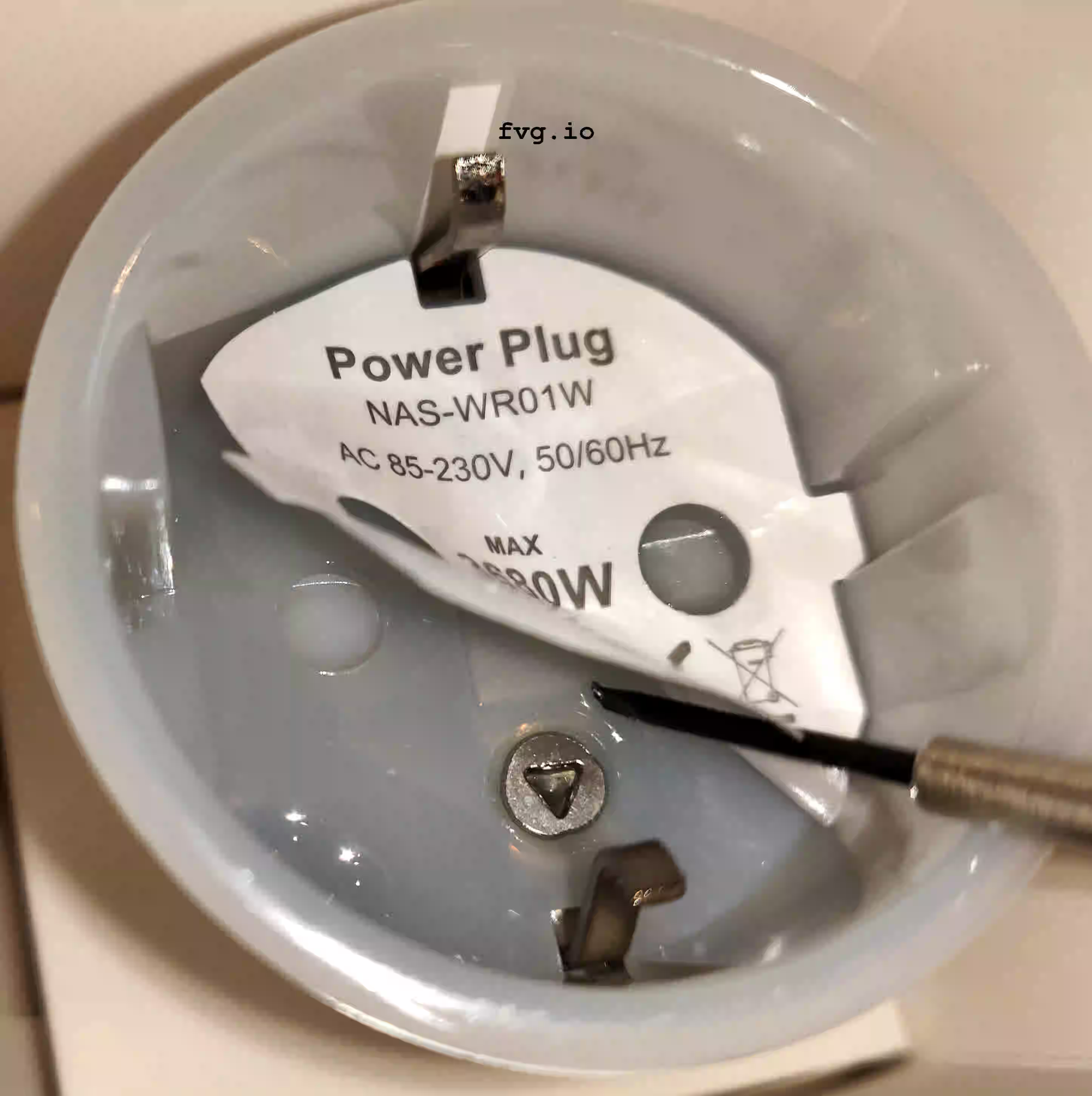
Ground PIN (GND) – The wire can be connected to the right side main contact of the plug. While pinned there, it won’t move too much (Fig. 4).
-
3.3V PIN (3V3) – There are a few points on the PCB to access the
3V3rail. I picked the left side of the two capacitors lying below the chip on the right side of the screw hole. I used one of the multimeter’s probes instead of a wire; balancing the probe in place was enough to maintain contact (Fig. 4).

- TXD –
The
TXDpin of the USB-serial adapter must be connected to theRXDpin of theESP8266(Fig. 2). I used the pin directly attached to theESP8266(Fig. 5). Extending the wire with a paperclip, or something similar, will make it easier to keep the electrical connection in place while holding the wire.

- RXD –
The
RXDpin of the USB-serial adapter must be connected to theTXDpin of theESP8266(Fig. 3). It is quite difficult to pinch theTXDpin directly on theESP8266while doing the same for theRXDpin. Instead, I followed the PCB track starting from theTXDpin, and I discovered that it is routed through a VIA, not far from the corner of the microcontroller (Fig. 6).

Since the VIA is round, more accessible and bigger than the track (or the pin), it makes for a better connection point. To access the via the solder mask that protects the PCB must be scraped away. I used a very small screwdriver with a sharp point; the surface layer of solder mask must be gently peeled away to reveal the copper below (Fig. 7).

I took my time doing this and frequently checked if I was scratching in the right spot and if any copper was visible.
Once done, it is possible to connect using a paperclip attached to the wire, as done for the RXD pin (Fig. 8).

Flashing with ESPHome
The ESP8266 can only be flashed with a new firmware when it’s in Download mode. This mode can be activated by pressing the smart plug button before applying tension to the microcontroller via the 3V3 and GND connections. Essentially the microcontroller should boot while the button is being pushed. If the button starts blinking red, it means that the plug is not in download mode, 3V3 or GND must be disconnected to retry.
I used esphome-flasher to flash the new firmware, but it is probably possible to achieve the same result using the ESPHome web-based flash utility with Google Chrome or Microsoft Edge.
🤔 Ok, ok..
Once finished transferring the new firmware, I left the 3V3 and GND cables connected, and double-checked that I had access to the smart plug by visiting its IP address using a browser (if using the internal web server) or via Home Assistant (if using the APIs).
If the plug is reachable, it’s then safe to disconnect all the cables and reassemble the plug cap.
Any subsequent update to the firmware can be performed over the air, so this flashing procedure should only be performed once.